

Using Draughtsman
Diagram types
Ten kinds of diagram, each drawn here in Draughtsman and exported as SVG from the editor. Nothing on this page is a mock-up.
Technically a document has one of four types, and the type picks the vocabulary of node and connector kinds: flowchart, architecture, freeform (no vocabulary, every shape family available) and sequence. ER, UML class, BPMN, swimlane, org chart and state diagrams are shape families that live inside those types, and the New diagram menu offers each as a starting point. That is why a BPMN process is a flowchart document and a UML class diagram is an architecture document. An agent asking get_schema for a type gets the exact kinds back.
Each figure below is the SVG the editor's Export SVG produced, drawn with the shipped neutral diagram theme so that it reads on white paper. Select a figure's link to open the SVG on its own, where the text is easier to read.
Flowchart
Processes, decisions, terminators, data, documents and the wider ISO 5807 symbol set (delay, manual operation, display, stored data, multi-document, merge, extract, summing junction, collate, sort, loop limit, internal storage, card and more). Decisions leave room for a long word. A flowchart document is also where BPMN, swimlane and state shapes are placed.
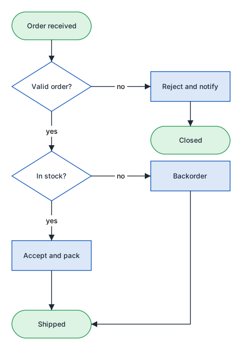
node n_start terminal "Order received" @ 200,40 160x56
node n_check decision "Valid order?" @ 200,140 160x100
edge e_1 flow n_start.bottom -> n_check.top routing=orthogonal
edge e_2 flow n_check.bottom -> n_stock.top "yes" routing=orthogonal
Architecture
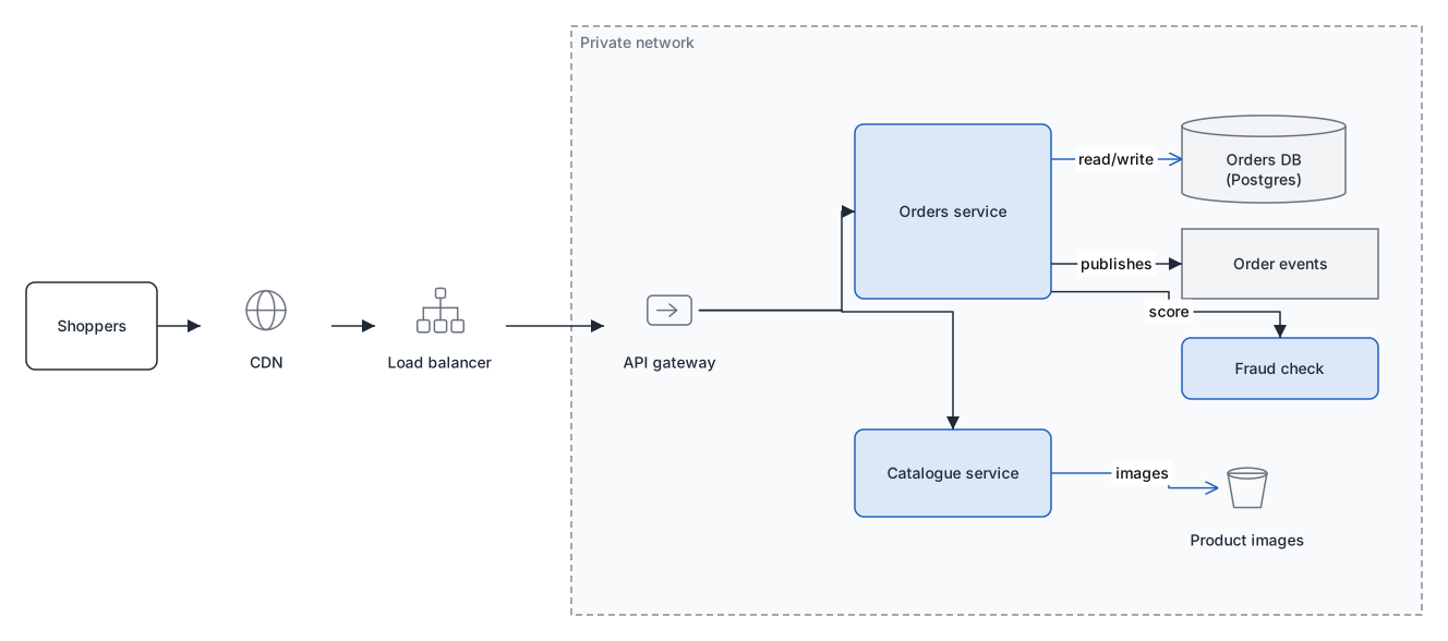
Services, databases, queues, actors, external systems, containers and notes, plus the generic technology icons: server, load balancer, API gateway, cache, CDN, firewall, object storage, function, router, switch, VPN, DNS, ingress, deployment and namespace objects, and VPC, subnet and availability-zone boundaries. A boundary icon draws as a labelled container with its artwork in a corner. Org-chart boxes, UML class shapes and database tables are available here too.
Freeform
No kind vocabulary at all: every shape family in the palette is available, and any kind word is accepted. Use it for a whiteboard-style picture that is not a flowchart or an architecture, or when you want to mix families. The trade-off is that the structural review has little to check.
Sequence
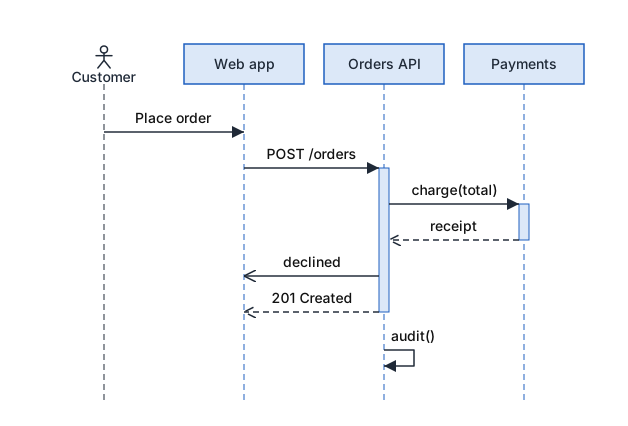
Participants are nodes and messages are connectors, and the order of the messages is time. No positions are stored: the layout is derived every time, so an agent only has to write the messages in the order they happen. Combined fragments (with operands and guards), notes, create and destroy, interaction use, activations and a stick-figure actor are supported. In the editor you add a message by dragging a connector between two lifelines, and reorder by dragging.
type sequence
node p_user actor "Customer"
node p_web participant "Web app"
node p_api participant "Orders API"
edge m_1 sync p_user -> p_web "Place order"
edge m_2 sync p_web -> p_api "POST /orders" activate=true
edge m_3 return p_api -> p_web "201 Created" deactivate=true
Fragments, notes, create and destroy
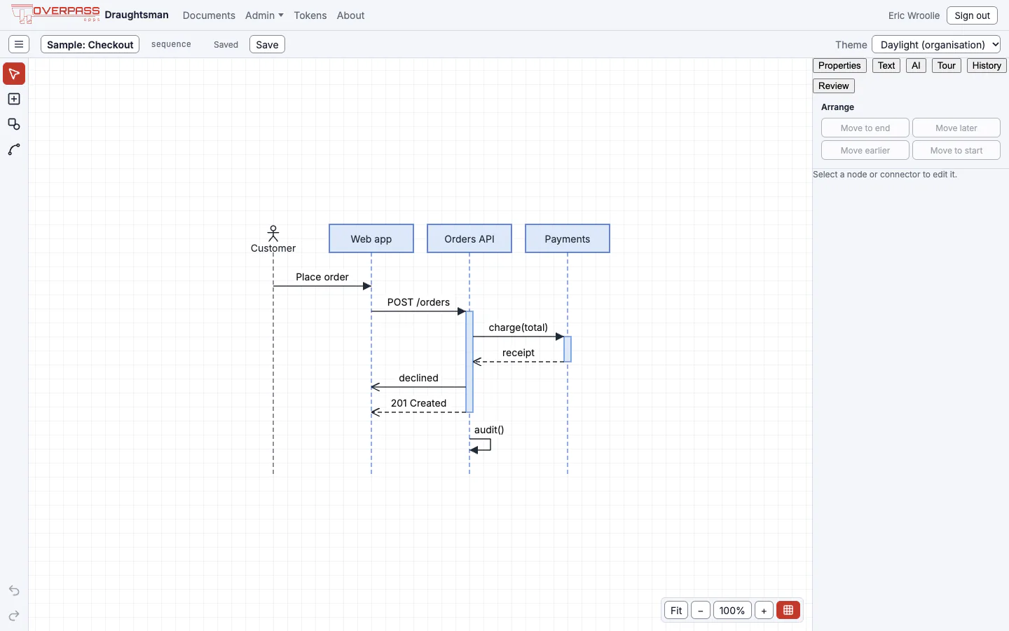
A fragment (the frame that says alt, opt, loop, par and so on) is a node of kind fragment that takes no column. Its tab text is the operator prop and its guards are the operands prop, one string per operand. Membership is written on each message, never on the fragment: in="f_1" and, for a message under a later operand, operand=1. The frame is derived from the first to the last member, and a fragment can nest in another. A note is an edge of kind note: a row in the time order whose label is the text. create is a message whose target's header is drawn at that row, and destroy ends the target's lifeline there with an X. The product's own example uses all four, and we opened it in the editor:

node f_1 fragment "alt" operator="alt" operands=["[card ok]","[declined]"]
edge n_1 note p_web -> p_api "Idempotent by key"
edge m_3 sync p_api -> p_pay "charge(total)" activate=true in="f_1" operand=0
edge m_5 async p_api -> p_web "declined" in="f_1" operand=1
edge m_7 create p_web -> p_mail "new Mailer()"
edge m_9 destroy p_web -> p_mail "close()"- Editing in the editor is by order. A sequence diagram has no free positions: you add a message by dragging a connector between two lifelines (the release point picks its slot), reorder by dragging a message or with Move earlier and Move later, and the editor works out which fragment a message falls in from its new neighbours. Resizing, free moving and waypoints are not offered for the type.
- The Text pane works for it too. A sequence diagram's order is the order of its lines: the nodes are the participants, left to right, and the edges are the messages, top to bottom. To add a message between two others, put its line between theirs. The Text pane applies it as one undo step.
- Mermaid in. A Mermaid
sequenceDiagramimports as asequencedocument; a construct Draughtsman cannot represent is one warning, while the messages inside it still import. Import Mermaid. - In a pull request, order is a change.
draughtsman diffreports a moved message as a change, because for a sequence diagram order is time (for other types it counts as layout). See Diagrams in git. - Agents.
patch_documenthas anaddEdgewithbeforeorafter, and amoveEdge, for exactly this. - Server-side rendering of a sequence diagram (
render_document, server PDF) needs the layout service running; the picture is drawn by the same code as the editor's.
What we ran: the editor on this example (the picture above) and the Text pane on it. The Mermaid import and the agent operations are described from Overpass's guide for this page; the Mermaid sequence import was run on the earlier build (see Import Mermaid), and we did not repeat it.
Entity-relationship (ER)
A database table is one node whose rows are its columns, written one per line in the form [PK] [FK] name type [not null | null]. Relationships are connectors with crow's-foot ends, and a connector can attach to a column's row rather than to the table box. You can build tables by hand, import them from SQL (T-SQL, PostgreSQL, MySQL, SQLite), or import Mermaid erDiagram text. A weak entity (a table whose primary key includes a foreign key) draws with a double border.
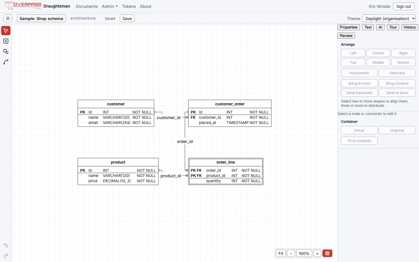
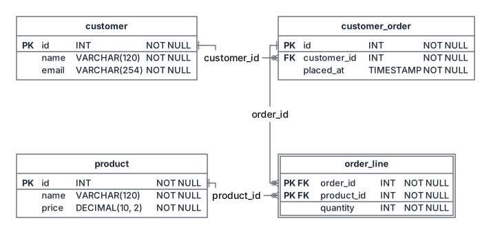
node t_customer entity "customer" @ 40,60 262x92 columns=["PK id INT not null","name VARCHAR(120) not null","email VARCHAR(254) not null"]
edge e_1 association t_customer_order.col:customer_id -> t_customer.col:id "customer_id" style.arrowStart=zeroOrMany style.arrowEnd=oneAndOnlyOne
UML class
A class or interface is one node: the label is its name, and its attributes and operations are lists, one member per line, with + - # ~ for visibility. The compartments are derived, so editing members refits the box as one undo step (double-click a compartment to edit it). Provided-interface (lollipop) and required-interface (socket) symbols are included, and the relationship line ends (inheritance, aggregation, composition, realisation, dependency) are connector styles.
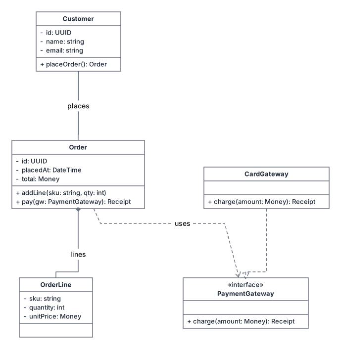
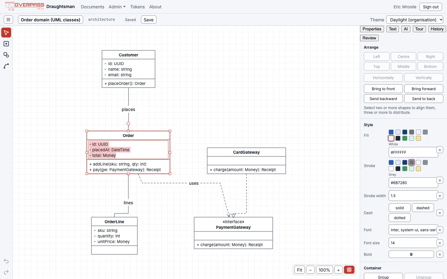
node c_order class "Order" attributes=["- id: UUID","- placedAt: DateTime","- total: Money"] operations=["+ addLine(sku: string, qty: int)"]
node c_gw interface "PaymentGateway" operations=["+ charge(amount: Money): Receipt"]
edge e_4 association c_card -> c_gw style.dash=dashed style.arrowEnd=inheritance
There is no separate "class diagram" document type, and no Mermaid classDiagram import.
BPMN
35 shapes: start, intermediate and end events (message, timer, signal, error, link and more), tasks (user, service, script, manual, send, receive, business rule), sub-process and call activity, five gateways, data objects and stores, and an annotation. Message flow, association and data association are connector kinds, and sequence flow is the ordinary flow. Events and gateways fill their box and put their label below it. Compensation, loop and multi-instance markers, several event types and choreography diagrams are deliberately left out.
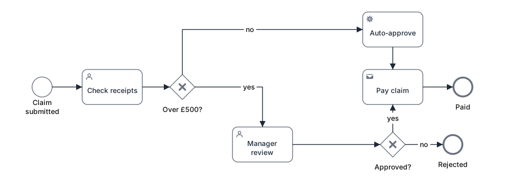
node n_start bpmn-start "Claim submitted" @ 40,170 40x40
node n_gate1 bpmn-exclusive-gateway "Over £500?" @ 315,165 50x50
edge e_4 flow n_gate1 -> n_mgr "yes" routing=orthogonal
Swimlane
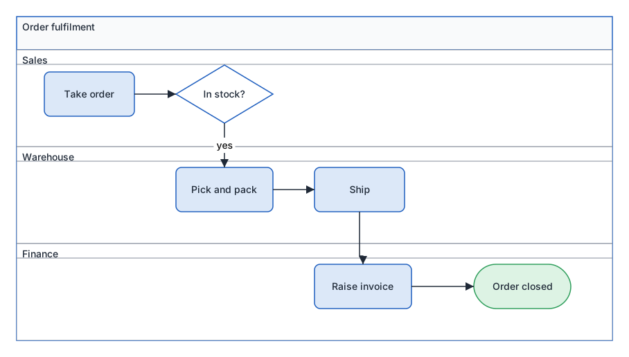
A pool is a container with a title band, and a lane is a band inside it. Lanes can run as rows or columns. Add, delete and reorder lanes from the editor, and resizing a pool repacks its lanes; a shape dropped into a lane becomes its child. Choose New Swimlane diagram and the pool arrives with two lanes at a working size.
Org chart
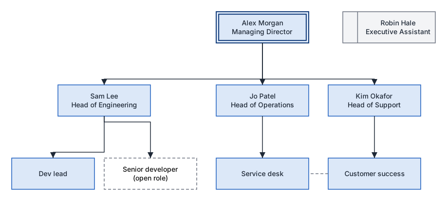
Four boxes: role (a plain box with a name over a title), executive (double border), assistant (a left spine, drawn beside its manager by the tree layout) and vacancy (dashed). A dotted-line report is the dotted-report connector. The tree layout (Tidy layout (Tree)) arranges it top-down.
State machine
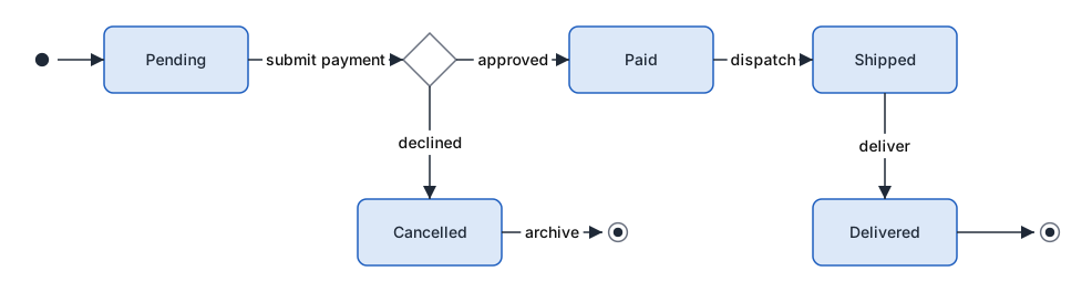
Nine UML pseudostate and composite shapes: initial, final, choice, fork/join (the one shape that resizes along one axis), shallow and deep history, entry and exit points, and composite state (a container with a name compartment). A plain rounded box is an ordinary state. The pseudostate glyphs are drawn from the shorter side of their box and hide their label.
How these were made
The documents were created through the product's own MCP create_document tool from the DSL, laid out by hand or by the ELK layout engine, adjusted with patch_document, and then exported with File, Export SVG in a real browser. The only edit to the SVG files is that a small subset of the Inter font is embedded in each, so the text keeps its shape when the SVG is shown as an image.